Exercise 8: Accurate collisions
Please complete Exercise 7 first, since the steps below build upon your work from that project.
In Exercise 7, we noticed that the red ball moves partway into the wall before bouncing. This slow motion video shows the problem:
Understanding the problem
The ball moves into the wall because our CHECK_COLLISION() function only tests a single point at the center of the ball:
FUNC CHECK_COLLISION(): BOOL
  VAR BOUNCE: BOOL
  FALSE -> BOUNCE

  # (FIND THE CENTER BY ADDING 8, SINCE OUR SPRITE IS 16 X 16)
  VAR CHECK_X, CHECK_Y
  .X + 8 -> CHECK_X
  .Y + 8 -> CHECK_Y

  VAR TILE_LAYER_B: TILE_LAYER
  ENGINE::TILE_LAYER_B -> TILE_LAYER_B

  # READ THE TILE NUMBER AT THE BALL'S CENTER
  VAR TILE
  TILE_LAYER_B.GET_TILE_AT_XY(CHECK_X, CHECK_Y) -> TILE

  IF TILE = 2 THEN # DIAMOND
    # ERASE THE DIAMOND WITH USING TILE #0
    TILE_LAYER_B.SET_TILE_AT_XY(CHECK_X, CHECK_Y, 0)
    SOUND::PLAY_TRACK(ID_SOUND::SOUND_0, 0)
    MAIN::DIAMOND_COUNT + 1 -> MAIN::DIAMOND_COUNT
  ELSIF TILE <> 0 THEN
    # THE BALL HIT A WALL OF SOME KIND
    TRUE -> BOUNCE
  END IF

  RETURN BOUNCE
END FUNC
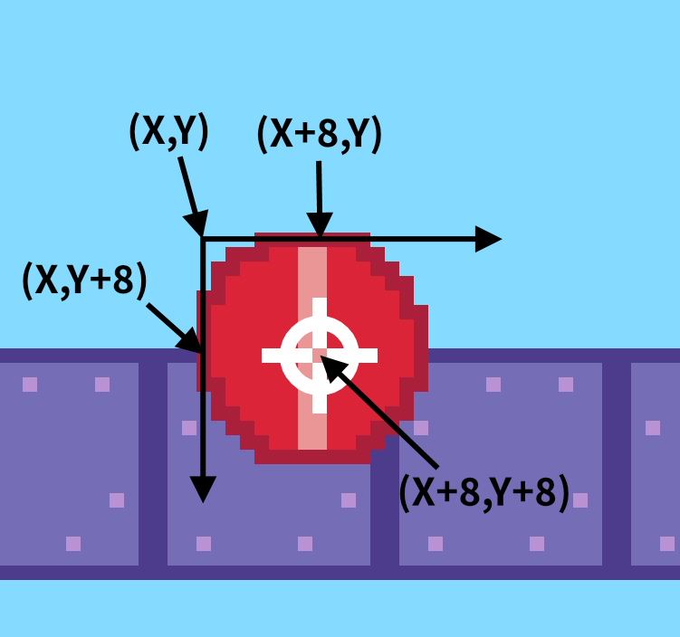
The diagram below shows where .X + 8 and .Y + 8 is located in our sprite image, at the moment when CHECK_COLLISION() decides to bounce:
For perfect accuracy, we would need to test every single point around the outer edge of the ball. That's a bit expensive, however. Performing too many checks might slow down our program. If we assume that the walls are relatively thick (not just isolated pixels), then we can get reasonably good accuracy by checking only a handful of points around the edge of the ball. The more points we check, the more accurate the bouncing will be.
Below is another diagram showing two points we could test, one at the top center of the ball (.X + 8 and .Y), and one at the bottom center (.X + 8 and .Y + 15). Keep in mind that the sprite dimensions are 16 × 16.

Testing these two points will make accurate bouncing for vertical collisions, but the above picture shows that the ball could still move horizontally into the wall. Let's start by writing code to test just these two points. (We'll improve it with more points later in step 32.)
Writing the code
-
Open your project called "BOUNCE BRIX" that you saved from Exercise 7. On the CODE screen, click the "NEW FILE" button to create a new file.
-
Click the pencil icon to rename the file from
FILE_0toEXPERIMENT: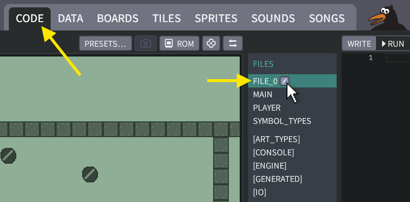
-
Add this code into the file:
The "EXPERIMENT" file:
CLASS POINT
  VAR X, Y
END CLASS

MODULE EXPERIMENT
  VAR POINTS: POINT[]
END MODULE

DATA EXPERIMENT::POINTS
[
  { X: 8, Y: 0 },
  { X: 8, Y: 15 }
]
END DATA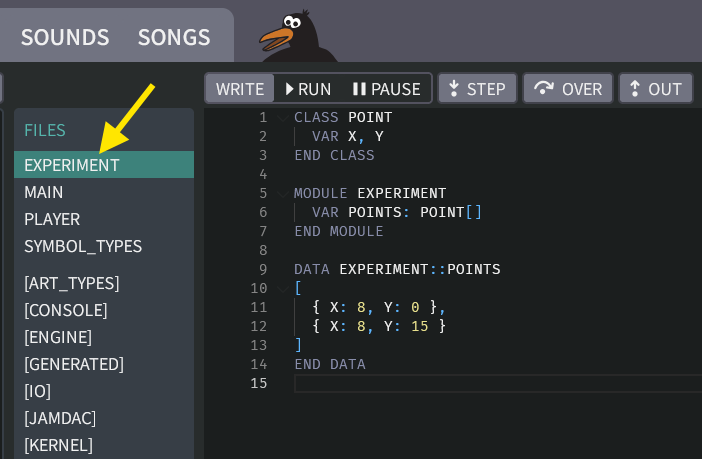

What does it do?
The code above declares a class called
POINTwhich we can use to represent our (X,Y) points that we will check for collisions.Then it makes an array called
EXPERIMENT::POINTSthat will hold a list of points. The object{ X: 8, Y: 0 }will handle the test for.X + 8and.Y. The object{ X: 8, Y: 15 }will handle the test for.X + 8and.Y + 15. Representing them as an array will make it easier for us to experiment with other locations later. -
Now we need to update the "PLAYER" file with a
LOOPthat will test each point fromEXPERIMENT::POINTS. The main idea is to replace this:.X + 8 -> CHECK_X
.Y + 8 -> CHECK_Y...with this:
.X + EXPERIMENT::POINTS[I].X -> CHECK_X
.Y + EXPERIMENT::POINTS[I].Y -> CHECK_Y
You don't need to write everything by hand, though. You could just copy and paste from the box below into your "PLAYER" file.
(Click to see the new code for the "PLAYER" file)
The "PLAYER" file:
  CLASS PLAYER EXTENDS ACTOR
    # REMEMBER THE BALL'S VELOCITY
    VAR DX
    VAR DY

    HOOK THINK()
      IF GAMEPAD::LEFT AND .DX >= -2 THEN
        .DX - 1 -> .DX
      END IF
      IF GAMEPAD::RIGHT AND .DX <= 2 THEN
        .DX + 1 -> .DX
      END IF
      IF GAMEPAD::UP AND .DY >= -2 THEN
        .DY - 1 -> .DY
      END IF
      IF GAMEPAD::DOWN AND .DY <= 2 THEN
        .DY + 1 -> .DY
      END IF

      # ADD THE BALL'S VELOCITY, MOVING THE BALL BY ONE STEP
      .X + .DX -> .X
      IF .CHECK_COLLISION() THEN
        .X - .DX -> .X  # UNDO OUR MOVE
        -.DX -> .DX     # BOUNCE
      END IF

      .Y + .DY -> .Y
      IF .CHECK_COLLISION() THEN
        .Y - .DY -> .Y  # UNDO OUR MOVE
        -.DY -> .DY     # BOUNCE
      END IF

      # MAKE THE CAMERA FOLLOW THE BALL
      ENGINE::SET_CAMERA_CX(.X)
      ENGINE::SET_CAMERA_CY(.Y)
    END HOOK

    FUNC CHECK_COLLISION(): BOOL
      VAR BOUNCE: BOOL
      FALSE -> BOUNCE

      VAR I
      0 -> I
      LOOP
        IF I >= EXPERIMENT::POINTS.SIZE
        DO DROP

        # (FIND THE CENTER BY ADDING 8, SINCE OUR SPRITE IS 16 X 16)
        VAR CHECK_X, CHECK_Y
        .X + EXPERIMENT::POINTS[I].X -> CHECK_X
        .Y + EXPERIMENT::POINTS[I].Y -> CHECK_Y

        VAR TILE_LAYER_B: TILE_LAYER
        ENGINE::TILE_LAYER_B -> TILE_LAYER_B


        # READ THE TILE NUMBER AT THE BALL'S CENTER
        VAR TILE
        TILE_LAYER_B.GET_TILE_AT_XY(CHECK_X, CHECK_Y) -> TILE

      IF TILE = 2 THEN # DIAMOND
        # ERASE THE DIAMOND WITH USING TILE #0
        TILE_LAYER_B.SET_TILE_AT_XY(CHECK_X, CHECK_Y, 0)
        SOUND::PLAY_TRACK(ID_SOUND::SOUND_0, 0)
        MAIN::DIAMOND_COUNT + 1 -> MAIN::DIAMOND_COUNT
      ELSIF TILE = 3 THEN # BRITTLE TILE
        TILE_LAYER_B.SET_TILE_AT_XY(CHECK_X, CHECK_Y, 0)
        TRUE -> BOUNCE
      ELSIF TILE = 4 THEN # EXIT TILE
        TRUE -> MAIN::REACHED_EXIT
      ELSIF TILE <> 0 THEN
        # THE BALL HIT A WALL OF SOME KIND
        TRUE -> BOUNCE
      END IF

      I + 1 -> I
    END LOOP

    RETURN BOUNCE
  END FUNC
END CLASS -
Click the "RUN" button to play your game. The red ball should now bounce accurately against its top and bottom, but horizontal bouncing will still go into the wall.
-
Try changing the array in your "EXAMPLE" file to experiment with other points. Here's some ideas:
Our original approach, testing just the ball's center:
DATA EXPERIMENT::POINTS
[
  { X: 8, Y: 8 }
]
END DATA
Testing the upper left corner:
DATA EXPERIMENT::POINTS
[
  { X: 0, Y: 0 }
]
END DATA
Testing the lower right corner:
DATA EXPERIMENT::POINTS
[
  { X: 15, Y: 15 }
]
END DATA
Testing the left and right edges:
DATA EXPERIMENT::POINTS
[
  { X: 0, Y: 8 },
  { X: 15, Y: 8 }
]
END DATA
Back to the drawing board
It's not easy to visualize
{ X: 15, Y: 8 }as the right edge of our ball. Wouldn't it be nicer to specify the geometry graphically, rather than typing in numbers by hand? Hybrix's boards system can do this! We just need to teach it how, by defining a new symbol type.
S_POINT
-
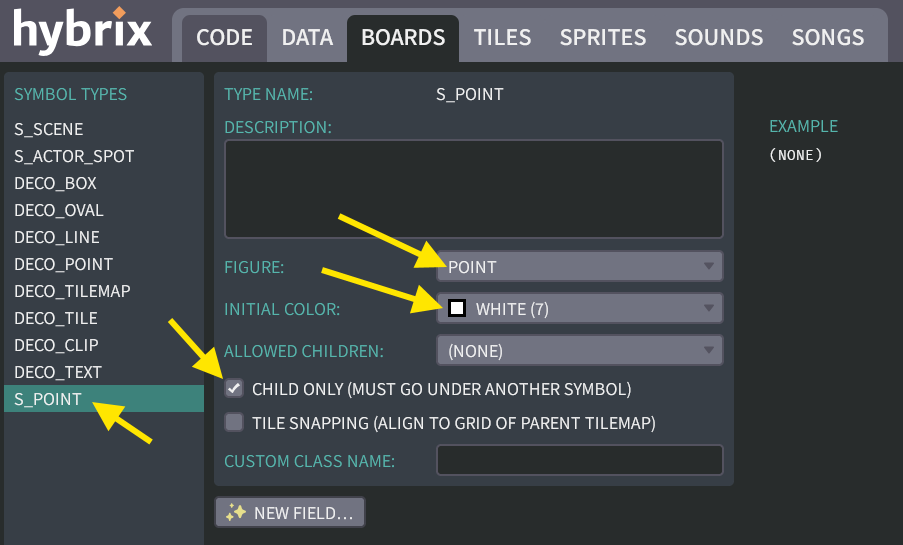
Go to the BOARDS screen, and click the "SYMBOL TYPES…" button. Then click the "NEW TYPE…" button. Click the pencil icon to rename the type from
SYMBOL_TYPE_0toS_POINT: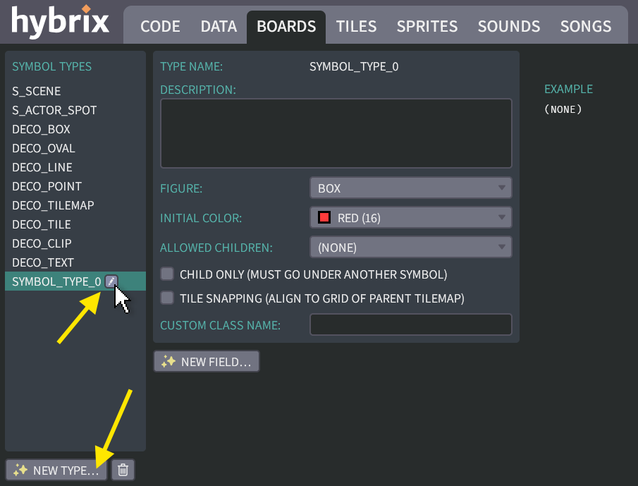
(We'll use this symbol type
S_POINTto represent the individual (X, Y) locations.) -
Make these changes:
- Change the "FIGURE" type from "BOX" to "POINT"
- Change the "INITIAL COLOR" to white (#7)
- Mark the checkbox for "CHILD ONLY".
The result should look like this:
-
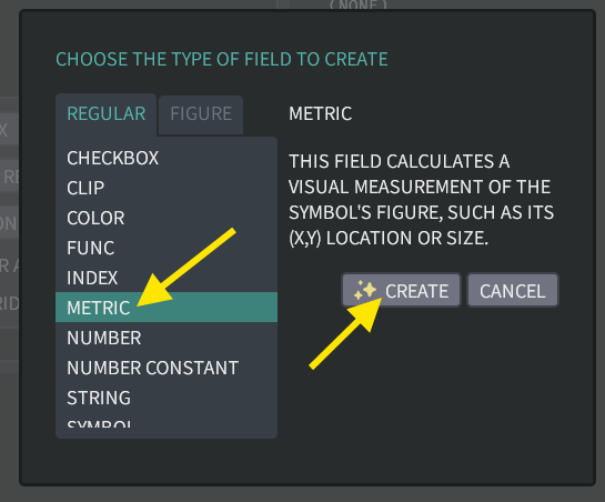
Click the "NEW FIELD…" button and choose the "METRIC" field type. Then click the "CREATE" button:
-
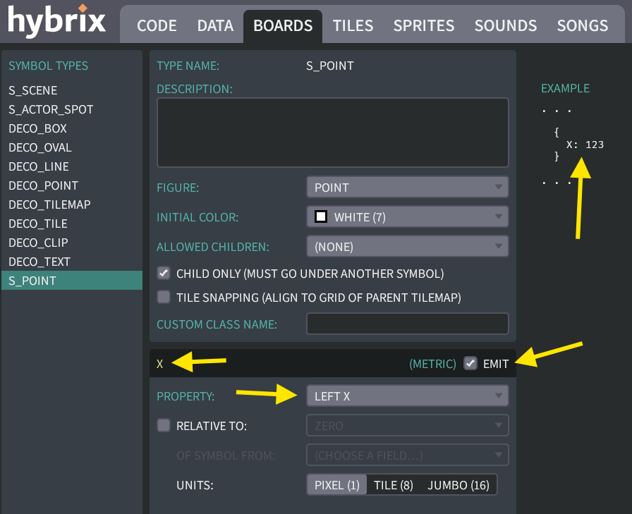
Click the pencil icon to rename the field from
FIELD_0toX: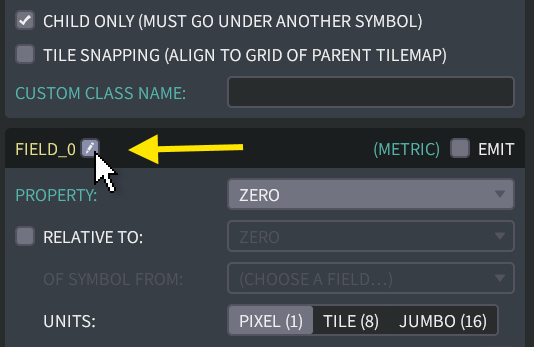
-
Also mark the checkbox for "EMIT". Change the property to "LEFT X". The result should look like this:
-
Now do the same operations to create a metric field named
Y, whose metric property is "TOP Y". The result should look like this: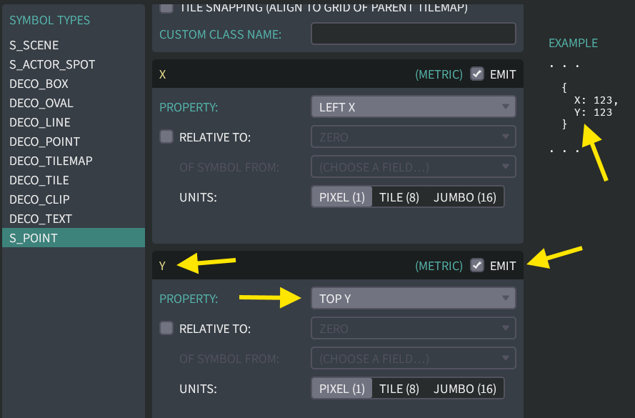
S_SPRITE_GEOMETRY
-
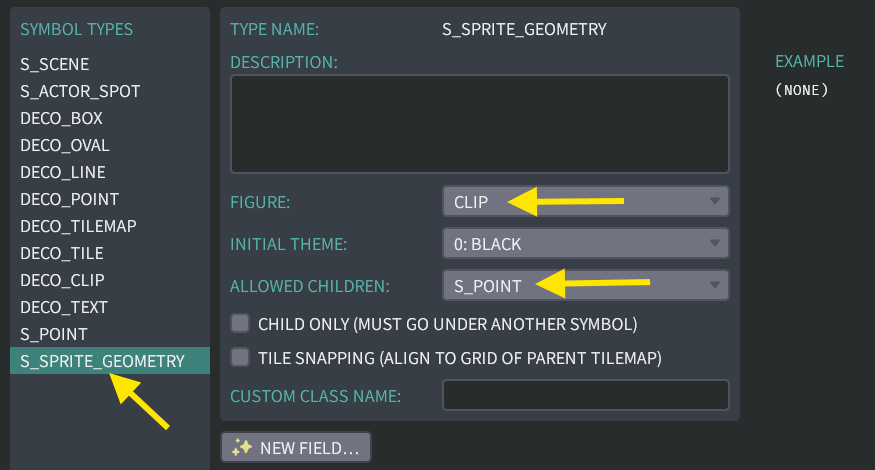
Then click the "NEW TYPE…" button to create a second symbol type. Click the pencil icon to rename the type from
SYMBOL_TYPE_0toS_SPRITE_GEOMETRY.Make these changes:
- Change the "FIGURE" type from "BOX" to "CLIP"
- Change the "ALLOWED CHILDREN" box to be
S_POINT.
The result should look like this:
-
Click the "NEW FIELD…" button and choose the "SYMBOL CHILDREN" field type. You will need to scroll down to find it.
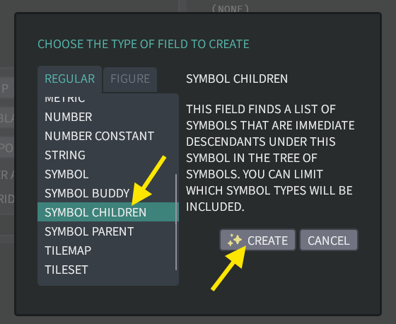
Click the "CREATE" button.
(We'll use this
S_SPRITE_GEOMETRYsymbol type to collect the array ofS_POINTobjects.) -
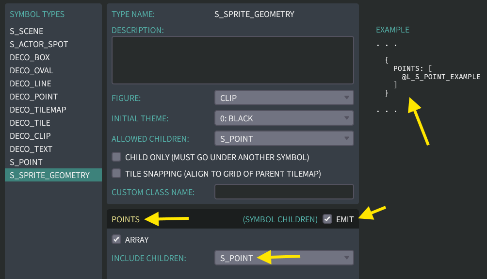
Click the pencil icon to rename the field from
FIELD_0toPOINTS. Also mark the checkbox for "EMIT". Change the "INCLUDE CHILDREN" box to beS_POINT.The result should look like this:
Creating the symbols
-
Click the "DONE" button to return to the BOARDS screen. Click the "NEW BOARD" button to create a new board. Click the pencil icon to rename this board from
BOARD_2toSPRITE_GEOMETRY: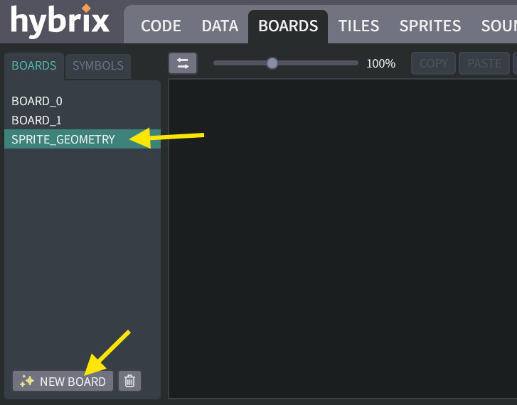
-
Click the "CREATE" button. Choose
S_SPRITE_GEOMETRYsymbol type. Then click in the middle of the board to create a new symbol: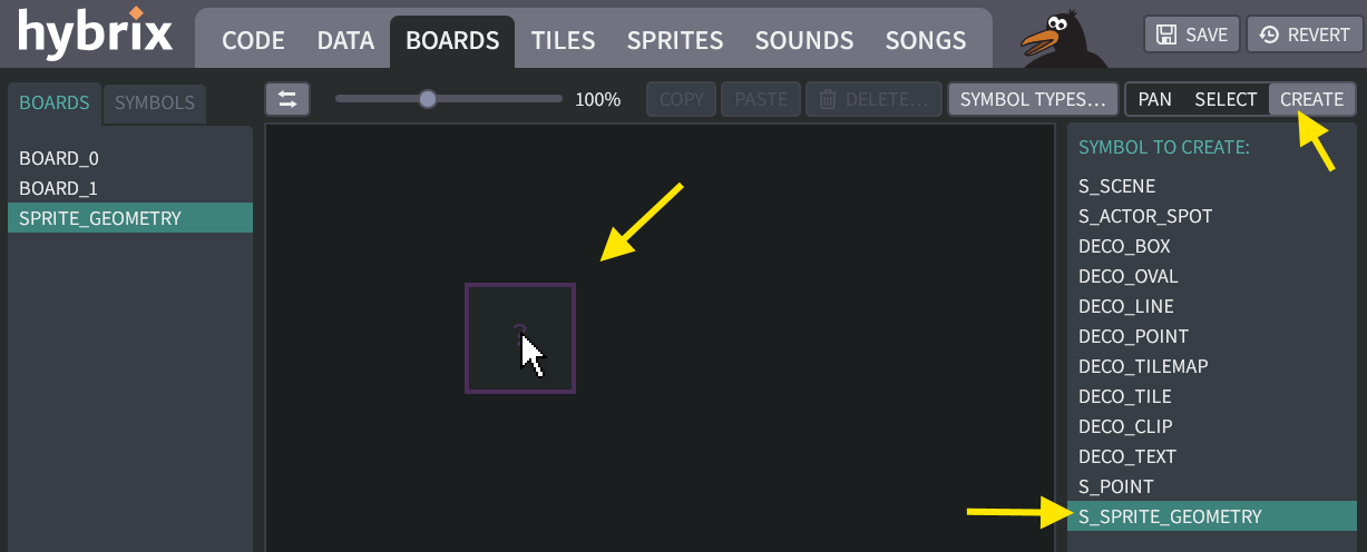
-
Click the "CHANGE…" button under "FIGURE CLIP", and choose
CLIP_0. The "?" box should change to show the red ball sprite as shown below: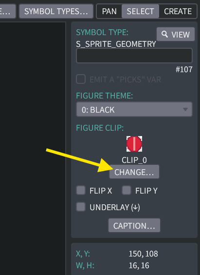
-
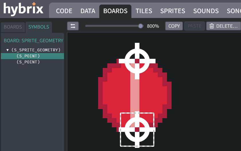
Next, click on the "SYMBOLS" tab to view the tree of symbols. Zoom in to 800% by using the zoom slider. To avoid the ball disappearing from view, make sure it is selected before zooming. (If your mouse has a scroll wheel, you can also zoom using the wheel while pressing the
CTRLkey on a PC, or while pressing theALTkey on a Mac.)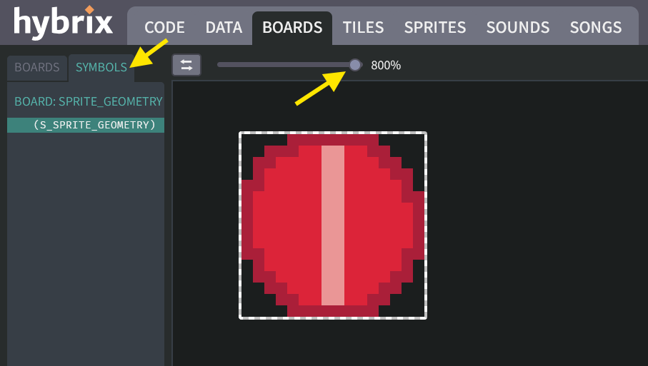
-
Then click the "CREATE" button and this time choose
S_POINT. (Don't confuse it withDECO_POINT!)Place the new point at the top of the ball. Then create a second point at the bottom of the ball. The result should look like this:
This is good start, but notice that the (X, Y) coordinates are too big. We expected them to be
{ X: 8, Y: 0 }and{ X: 8, Y: 15 }, but in the screenshot below they are{ X: 162, Y: 137 }. That's way outside the sprite's 16 × 16 grid! (Your numbers may be different—it depends on where your sprite is positioned on the board.)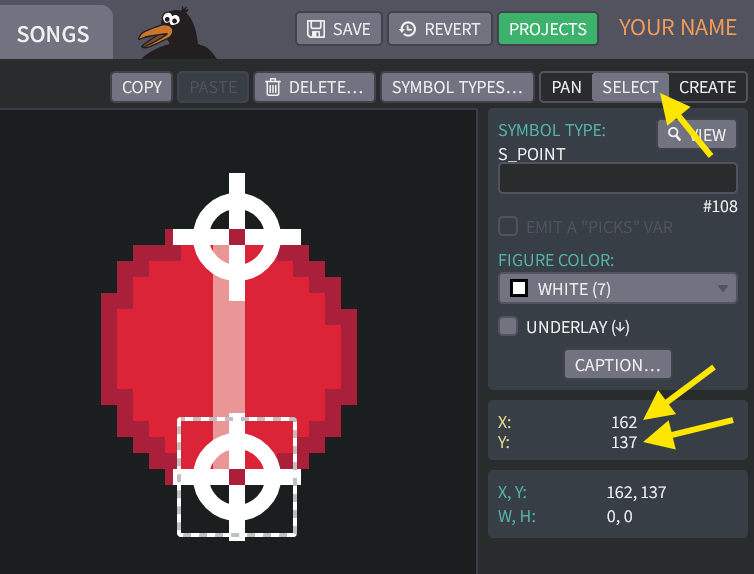
The problem is that these coordinates measure from (0, 0) at the center of board, which is generally NOT the upper left corner of the sprite for
S_SPRITE_GEOMETRY. How to fix that? -
Click the "SYMBOL TYPES…" button again and select
S_POINT. Click the "NEW FIELD…" button and choose the "SYMBOL PARENT" field type. Then click the "CREATE" button: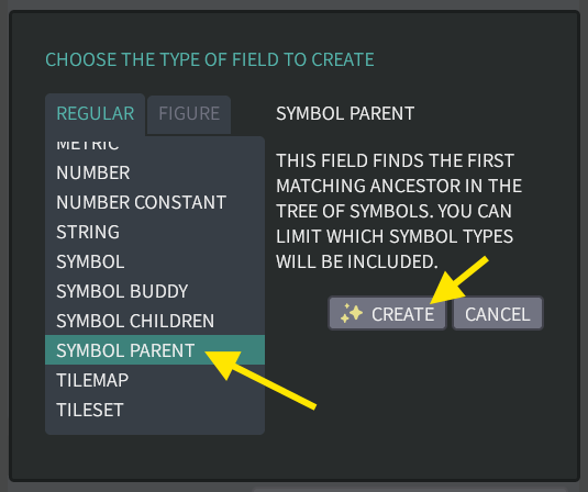
-
Rename the new field from
FIELD_0toPARENT_GEOMETRY. Change its "PARENT TYPE" box to beS_SPRITE_GEOMETRY.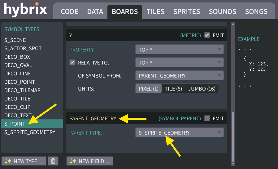
👉 Do not mark the "EMIT" checkbox. Our code won't need the
PARENT_GEOMETRYfield; it's just a helper for calculating the metric fields. -
Find the panel for the
Xfield ofS_POINT. Mark the checkbox for "RELATIVE TO", and specify "LEFT X". For the "OF SYMBOL FROM" box, specify thePARENT_GEOMETRYfield.The result should look like this:
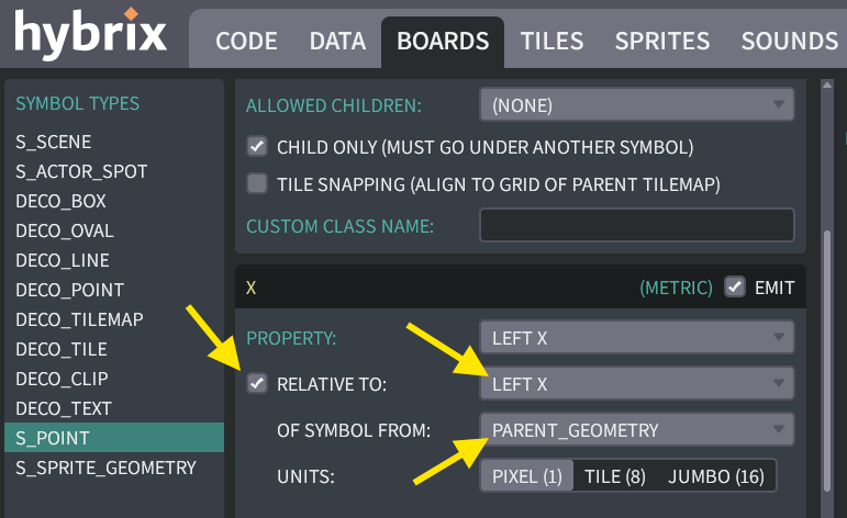
-
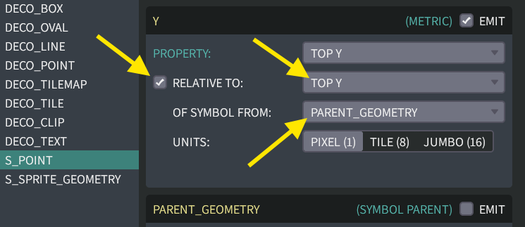
Find the panel for the
Yfield ofS_POINT. Mark the checkbox for "RELATIVE TO", and specify "TOP Y". For the "OF SYMBOL FROM" box, specify thePARENT_GEOMETRYfield.The result should look like this:
What does "relative to" mean?
In the symbol tree, the
S_POINTsymbols are children under theS_SPRITE_GEOMETRYsymbol:
For each point, the
S_POINTsymbol'sPARENT_GEOMETRYfield looks upwards in the tree to find theS_SPRITE_GEOMETRYsymbol. Then ourXandYfields will be measured relative to that symbol, rather than relative to the board. "Relative to" means (0,0) is now the upper-left corner of the sprite, rather than the center of the board. -
Click the "DONE" button to return to the board. Now the point's coordinates show
{ X: 0, Y: 15 }forXandY, the correct values!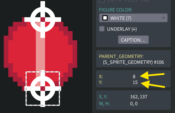
The
XandYfield names appear in yellow. Below that, another panel shows greenish-blue labels "X, Y"; these are figure properties measured using board coordinates. The panel also shows the figure's width and height properties, labeled "W, H". The colors help us avoid confusing field names (defined by you in your symbol type) versus figure properties (whose names are just informational labels). -
To see how the "relative to" math works, hover your mouse cursor over the yellow "X" field name. A tooltip appears, showing that the relative value 8 was calculated by subtracting 162 (the point's X in board coordinates) minus 154 (the sprite's X in board coordinates).

Putting it all together
Now that we can visually specify our points, we just need to get them into our code.
-
Select the red ball and type in a name
BALL_GEOMETRY. Then mark the checkbox for "EMIT A PICKS VAR".
-
Go to the DATA screen, then click on the "PICKS" tab. Now we can see that Step 27 automatically created a symbol pick called
SYMBOLS::BALL_GEOMETRYthat contains our points: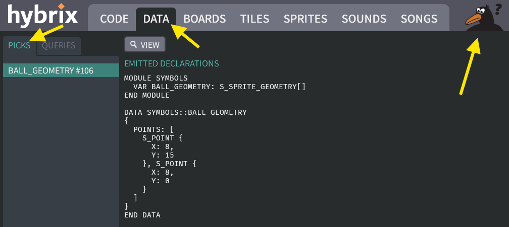
Crow Dan is unhappy because the
S_SPRITE_GEOMETRYclass doesn't exist yet. We'll fix that in the next step.MODULE SYMBOLS
VAR BALL_GEOMETRY: S_SPRITE_GEOMETRY[]
END MODULE
DATA SYMBOLS::BALL_GEOMETRY
{
POINTS: [
S_POINT {
X: 8,
Y: 15
}, S_POINT {
X: 8,
Y: 0
}
]
}
END DATA -
Go to the CODE screen, and open the "SYMBOL_TYPES" file. Add these lines to the top:
CLASS S_SPRITE_GEOMETRY
  VAR POINTS: S_POINT[]
END CLASS

CLASS S_POINT
  VAR X, Y
END CLASS
This should eliminate the compiler error.
(Click to see the full code for the "SYMBOL_TYPES" file)
The "SYMBOL_TYPES" file:
CLASS S_SPRITE_GEOMETRY
  VAR POINTS: S_POINT[]
END CLASS

CLASS S_POINT
  VAR X, Y
END CLASS

# -----------------------------------------------------------------------------
# THIS BOARD SYMBOL PLACES AN ACTOR AT A GIVEN SPOT WHEN THE SCENE IS LOADED.
CLASS S_ACTOR_SPOT
  VAR X: INT
  VAR Y: INT
  VAR ACTOR_FACTORY: ACTOR_FACTORY
  VAR STARTING_CLIP: CLIP
  VAR THEME: BYTE
  VAR FLIP_X: BOOL, FLIP_Y: BOOL, ROTATE: BOOL
END CLASS

# -----------------------------------------------------------------------------
# THE "S_SCENE" BOARD SYMBOL SPECIFIES A TILEMAP AND A COLLECTION OF ACTORS.
CLASS S_SCENE
  VAR TITLE: STRING
  VAR TILEMAP: TILEMAP
  VAR TILESET: TILESET
  VAR ACTOR_SPOTS: S_ACTOR_SPOT[]
  VAR BACKGROUND_COLOR: BYTE

  # ---------------------------------------------------------------------------
  FUNC LOAD()
    VAR TILESET: TILESET
    VAR TILEMAP: TILEMAP

    .TILEMAP -> TILEMAP
    .TILESET -> TILESET

    # FREE THE MEMORY FROM THE OLD TILEMAP COPY
    ENGINE::CLEAR_ACTORS()
    ENGINE::TILE_LAYER_B.LOAD_TILEMAP(NULL)

    IF TILEMAP <> NULL AND TILESET <> NULL THEN
      VAR TILEMAP_COPY: TILEMAP
      NEW TILEMAP() -> TILEMAP_COPY
      TILEMAP_COPY.COPY_FROM(TILEMAP)
      ENGINE::TILE_LAYER_B.LOAD_TILEMAP(TILEMAP_COPY)
      ENGINE::TILE_LAYER_B.LOAD_TILESET(TILESET)
    END IF

    ENGINE::LOAD_ACTOR_SPOTS(.ACTOR_SPOTS)

    IF .BACKGROUND_COLOR > 0 THEN
      .BACKGROUND_COLOR -> IO::BACKGROUND_COLOR
    END IF
  END FUNC
END CLASS -
Open the "PLAYER" file. The last fix is to replace
EXPERIMENT::POINTSwithSYMBOLS::BALL_GEOMETRY.POINTS. To make the code more efficient, we can put it into a local variable calledPOINTS:VAR POINTS: S_POINT[]
SYMBOLS::BALL_GEOMETRY.POINTS -> POINTS(Click to see the finished PLAYER file)
The "PLAYER" file:
CLASS PLAYER EXTENDS ACTOR
# REMEMBER THE BALL'S VELOCITY
VAR DX
VAR DY
HOOK THINK()
IF GAMEPAD::LEFT AND .DX >= -2 THEN
.DX - 1 -> .DX
END IF
IF GAMEPAD::RIGHT AND .DX <= 2 THEN
.DX + 1 -> .DX
END IF
IF GAMEPAD::UP AND .DY >= -2 THEN
.DY - 1 -> .DY
END IF
IF GAMEPAD::DOWN AND .DY <= 2 THEN
.DY + 1 -> .DY
END IF
# ADD THE BALL'S VELOCITY, MOVING THE BALL BY ONE STEP
.X + .DX -> .X
IF .CHECK_COLLISION() THEN
.X - .DX -> .X # UNDO OUR MOVE
-.DX -> .DX # BOUNCE
END IF
.Y + .DY -> .Y
IF .CHECK_COLLISION() THEN
.Y - .DY -> .Y # UNDO OUR MOVE
-.DY -> .DY # BOUNCE
END IF
# MAKE THE CAMERA FOLLOW THE BALL
ENGINE::SET_CAMERA_CX(.X)
ENGINE::SET_CAMERA_CY(.Y)
END HOOK
FUNC CHECK_COLLISION(): BOOL
VAR BOUNCE: BOOL
FALSE -> BOUNCE
VAR POINTS: S_POINT[]
SYMBOLS::BALL_GEOMETRY.POINTS -> POINTS
VAR I
0 -> I
LOOP
IF I >= POINTS.SIZE
DO DROP
# (FIND THE CENTER BY ADDING 8, SINCE OUR SPRITE IS 16 X 16)
VAR CHECK_X, CHECK_Y
.X + POINTS[I].X -> CHECK_X
.Y + POINTS[I].Y -> CHECK_Y
VAR TILE_LAYER_B: TILE_LAYER
ENGINE::TILE_LAYER_B -> TILE_LAYER_B
# READ THE TILE NUMBER AT THE BALL'S CENTER
VAR TILE
TILE_LAYER_B.GET_TILE_AT_XY(CHECK_X, CHECK_Y) -> TILE
IF TILE = 2 THEN # DIAMOND
# ERASE THE DIAMOND WITH USING TILE #0
TILE_LAYER_B.SET_TILE_AT_XY(CHECK_X, CHECK_Y, 0)
SOUND::PLAY_TRACK(ID_SOUND::SOUND_0, 0)
MAIN::DIAMOND_COUNT + 1 -> MAIN::DIAMOND_COUNT
ELSIF TILE = 3 THEN # BRITTLE TILE
TILE_LAYER_B.SET_TILE_AT_XY(CHECK_X, CHECK_Y, 0)
TRUE -> BOUNCE
ELSIF TILE = 4 THEN # EXIT TILE
TRUE -> MAIN::REACHED_EXIT
ELSIF TILE <> 0 THEN
# THE BALL HIT A WALL OF SOME KIND
TRUE -> BOUNCE
END IF
I + 1 -> I
END LOOP
RETURN BOUNCE
END FUNC
END CLASS -
With these changes, we're no longer using the code from the
EXPERIMENTSsource file. You can delete that file: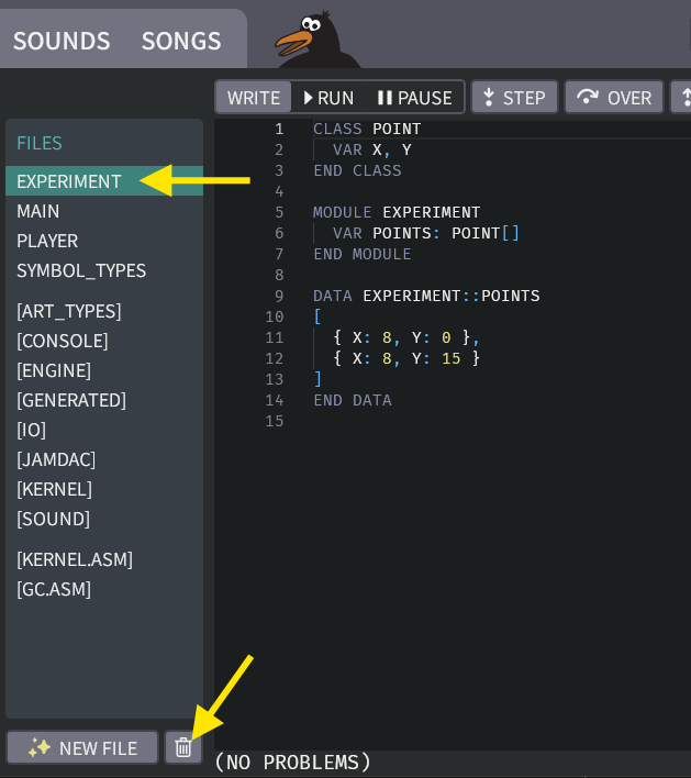
Then click the "RUN" button to confirm that your program still works.
-
Now we can finally improve our bouncing to be more accurate! Go back to the BOARDS tab, and add more points around the edge of the ball:
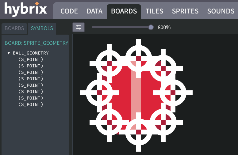
It should now bounce correctly without going into the wall. You can now experiment with other placements of points to see how it affects the bouncing.
Great job! You've come a long way!
That's all for Exercise 8. In the next exercise, we'll add some other actors to make the maze more fun.